


Four bit binary counter pic
Description
Today's lab session is about binary counting LEDs. The binary 1 and 0 will be represented by turning LEDs on and off. You will make a 4-bit binary counter (using 4 LEDs) that counts from 0 to 15 (0000-1111 binary). The four LEDs are connected to RC0 through RC3 port pins of PIC16F688 with current limiting resistors (470Ω each) in series. A push button switch is connected to pin RC4 to provide input for the counter. The counter starts from 0, and increase by 1 every time the button is pressed. When the counter reaches 15 (all LEDs on), it will reset to 0 on the next press of the button.
Required Theory
You should be familiar with the digital I/O ports of PIC16F688 and their direction settings. If you are not, read Digital I/O Ports in PIC16F688. Read previous lab session (Lab 2: Basic digital input and output) to learn about reading inputs from a push button.
Circuit Diagram
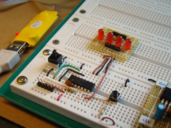
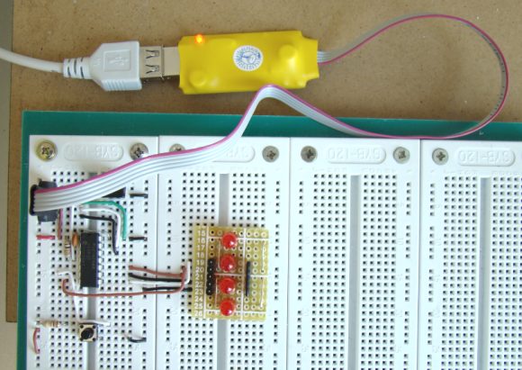
The circuit diagram and its construction on the breadboard are shown in figures below. The PIC16F688 microcontroller uses its internal clock at 4.0 MHz.

Software
Define PORTC pins RC0-RC3 as output, and the pin RC4 as an input. Disable comparators (CMCON0=7), and configure all I/O pins as digital (ANSEL=0). Use Button() function to read input from the push button switch.
/* Lab 3: 4-bit up counter Internal Clock @ 4MHz, MCLR Enabled, PWRT Enabled, WDT OFF Copyright @ Rajendra Bhatt Nov 6, 2010 */ // Define Tact switch @ RC4 sbit Switch at RC4_bit; // Define button Switch parameters #define Switch_Pin 4 #define Switch_Port PORTC #define Debounce_Time 20 // Switch Debounce time 20ms unsigned short count; void main() { ANSEL = 0b00000000; //All I/O pins are configured as digital CMCON0 = 0x07 ; // Disbale comparators TRISC = 0b00010000; // PORTC all output except RC4 TRISA = 0b00001000; // PORTA All Outputs, Except RA3 count = 0; PORTC = count; do { if (Button(&Switch_Port, Switch_Pin, Debounce_Time, 0)) { if (!Switch) { count ++; if (count ==16) count =0; PORTC = count; } while (!Switch); // Wait till the button is released } } while(1); // Infinite Loop } Output
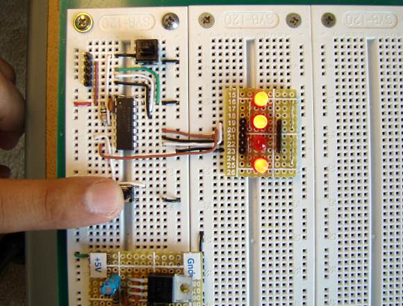
The counter starts from 0 (all LEDs off), and is incremented by 1 on every button press. After it reaches 15, it overflows and takes the next value 0. This repeats forever.
--
With Regards,
s.m.sethupathy,
sms communication,
Tanjore -1.
mobile :9944 186 173
www.questionpaperlink.co.cc
www.sethu-panguvarthagam.blogspot.com
Digital I/O Ports in PIC16F688
PIC16F688 is a 14-pin flash-based, 8-bit microcontroller. It can be obtained in different packages, but the DIP (Dual In-line Package) version is recommended for prototyping. The figure below shows a PIC16F688 microcontroller in DIP chip, and its pin outs.

Most of the pins are for input and output, and are arranged as PORTA (6) and PORTC (6), giving a total of 12 I/O pins. All of these can operate as simple digital I/O pins but they do have more than one function. For example, eight of total 12 I/O pins also serve as analogue inputs for the internal analog-to-digital converter (ADC). Similarly, the PORTA pins RA0 and RA1 are also used to serially load an user program into the PIC16F688 flash memory. The mode of operation of each pin is selected by initializing various control registers inside the chip. All these options will be discussed later on.
PORTA
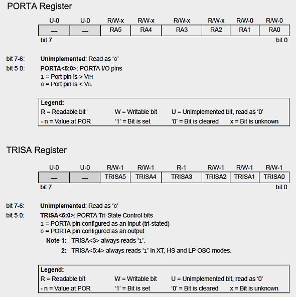
PORTA is a 6-bit wide, bidirectional port. A bidirectional port is one that can act as either an input port, to receive information from external circuitry, or an output port, to give information to external circuitry. The direction of the PORTA pins is controlled by the TRISA register. Setting a TRISA bit (= 1) will make the corresponding PORTA pin an input, and clearing a TRISA bit (= 0) will make the corresponding PORTA pin an output. The RA3 pin is an exception because it is input only and so its TRISA bit will always read as '1'. The TRISA register controls the direction of the PORTA pins, even when they are being used as analog inputs. Therefore, the user must ensure the bits in the TRISA register are maintained set when using them as analog inputs. I/O pins configured as analog input always read '0'.
PORTC
Similar to PORTA, PORTC also has 6 bidirectional I/O pins. Each of the pin can be selected as input or output by setting or clearing the corresponding bit in the TRISC register.
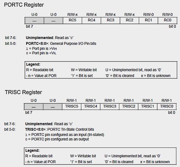
Important
PIC16F688 has two analog voltage comparators and eight 10-bit ADC channels. The inputs to the comparators are multiplexed with I/O port pins RA0, RA1, RC0 and RC1, while the outputs are multiplexed to pins RA2 and RC4. On a power-on reset, RA0, RA1, RC0, and RC1 are configured as analog inputs, as controlled by the CMCON0 register. In order to use these pins as digital inputs, the comparators must be turned OFF. This can be done by assigning decimal value 7 to CMCON0 register (CMCON0=0b00000111).
Similarly, the PIC16F688 port pins that are multiplexed with ADC channel inputs are also configured as analog inputs on a power-on reset. The ANSEL register must be initialized to decimal 0 (ANSEL=0b00000000) to configure all ADC channels as digital inputs. The CMCON0 and ANSEL registers will be discussed in more detail later.
--
With Regards,
s.m.sethupathy,
sms communication,
Tanjore -1.
mobile :9944 186 173
www.questionpaperlink.co.cc
www.sethu-panguvarthagam.blogspot.com
Flashing an LED PIC
Description
Today is our first session in PIC microcontroller lab, and we will begin with an experiment that flashes an LED on and off. While this looks very simple it is the best project to start because this makes sure that we successfully wrote the program, compiled it, loaded inside the PIC, and the circuit is correctly built on the breadboard.
In this lab session we will connect an LED to one of the port pin of PIC16F688 and flash it continuously with 1 sec duration.
Required Theory
You must be familiarized with,
- digital I/O ports (PORTA and PORTC) of PIC16F688
- direction control registers, TRISA and TRISC
- special function registers CMCON0 and ANSEL
If you are not then please read this first: Digital I/O Ports in PIC16F688.
Circuit Diagram
To our basic setup on the breadboard (read Getting Ready for the First Lab), we will add a light-emitting-diode (LED) to port pin RC0 (10) with a current limiting resistor (470 Ohm) in series. The complete circuit diagram is shown below.

Flashing LED circuit

Prototyped circuit on the breadboard
Software
Open a new project window in mikroC and select Device Name as PIC16F688. Next assign 4.0 MHz to Device Clock. Go to next and provide the project name and the path of the folder. It is always a good practice to have a separate folder for each project. Create a folder named Lab1 and save the project inside it with a name (say, FlashLED). The mikroC project file has .mccpi extension. The next window is for "Add File to Project ". Leave it blank (there are no files to add to this project) and click next. The next step is to include libraries, select Include All option. Next, click Finish button. You will see a program window with a void main() function already included. Now, go to Project -> Edit Project. You will see the following window.
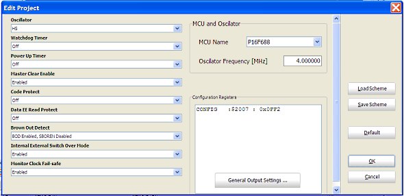
This window allows you to program the configuration bits for the 14-bit CONFIG register inside the PIC16F688 microcontroller. The device configuration bits allow each user to customize certain aspects of the device (like reset and oscillator configurations) to the needs of the application. When the device powers up, the state of these bits determines the modes that the device uses. Therefore, we also need to program the configuration bits as per our experimental setup. Select,
Oscillator -> Internal RC No Clock
Watchdog Timer -> Off
Power Up Timer -> On
Master Clear Enable -> Enabled
Code Protect -> Off
Data EE Read Protect -> Off
Brown Out Detect -> BOD Enabled, SBOREN Disabled
Internal External Switch Over Mode -> Enabled
Monitor Clock Fail-Safe -> Enabled
Note that we have turned ON the Power-Up Timer. It provides an additional delay of 72 ms to the start of the program execution so that the external power supply will get enough time to be stable. It avoids the need to reset the MCU manually at start up.
Read PIC16F688 datasheet for details on Configuration Word.
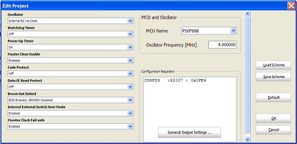
Appropriate configuration bit selection
Here's the complete program that must be compiled and loaded into PIC16F688 for flashing the LED. Copy and paste this whole program in your main program window. You have to delete the void main() function first that was already included. To compile, hit the build button, and if there were no errors, the output HEX file will be generated in the same folder where the project file is. Then load the HEX file into the PIC16F688 microcontroller using your programmer.
Output
You will see the LED flashing On and Off with 1 sec duration.

--
With Regards,
s.m.sethupathy,
sms communication,
Tanjore -1.
mobile :9944 186 173
www.questionpaperlink.co.cc
www.sethu-panguvarthagam.blogspot.com
Play musical notes PIC
We have discussed in the past experiments how to use a PIC microcontroller to do a variety of things from flashing an LED to driving a motor, etc. Today, we will see how to play notes of a song with a PIC microcontroller. Musical notes are simply sound waves of particular frequencies. If the frequency of a note is known correctly, a microcontroller can be programmed to play the note by generating a square wave (of the same frequency) signal at one of its I/O pins. The signal must be fed to a speaker to listen to the sound. Here, we will discuss playing notes of the popular "Happy birthday to you" tune using a PIC16F628A microcontroller and a buzzer.
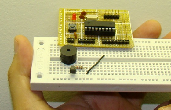
Musical notes using a PIC micro
Theory
In order to play the tune of a song, you need to know its musical notes. Each note is played for a certain duration and there is a certain time gap between two successive notes. The table below provides frequencies of musical notes starting from middle C. The middle C is designated as C4 because it is the fourth C key on a standard 88-key piano keyboard.

Musical notes and their frequencies starting from Middle C
The notes of the other octaves can be obtained by multiplying or dividing these frequencies by 2. For example, the next C note above the middle C would have a frequency of 524 Hz. You can find the frequencies of rest of the notes at the following link: http://cs.nyu.edu/courses/fall03/V22.0201-003/notes.htm
Musical notes can be generated using square waves of the note frequencies. So, in order to play the tune of a song with a microcontroller, all you need to know are the musical notes and their timing information; rest is all programming. A square wave can be generated at an I/O pin of PIC microcontroller by bit-banging the pin high and low. An alternative way of achieving this is using a hardware PWM module. Here, we will be using the former one.
Circuit diagram
The circuit diagram for this experiment is pretty simple. The RB0 pin of the PIC16F628A microcontroller is bit-banged to generate a square wave tone of desired frequency. An I/O pin of PIC16F628A can source current up to 25 mA, which may not be sufficient to drive an electric buzzer directly. Therefore, a BC547 NPN transistor is used as a current amplifier for the buzzer. An RC filtering may be used to improve the quality of audio (square waves are not pure waves and so they don't sound as good as sine waves), but for simplicity, it is not implemented here.
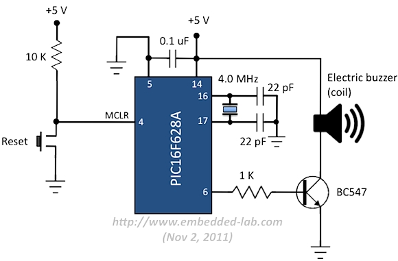
Electrical coil buzzer is driven through RB0 pin using a transistor
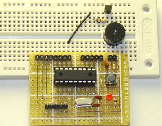
Circuit setup on breadboard
You can see I am using my PIC16F628A breadboard module in this experiment.
Software
Generating audio tones is very easy in mikroC Pro for PIC compiler. It has a built-in Sound Library for serving this purpose. The library has following two functions:
Sound_Init(char *snd_port, char snd_pin): Configures the appropriate MCU pin for sound generation. For example, Sound_Init(&PORTB,0) will configure RB0 pin for the sound output.
Sound_Play(unsigned freq_in_hz, unsigned duration_ms): Generates a square wave signal on the appropriate pin.
The note frequencies of a song can be either defined as a variable array or saved as a constant array in ROM (if RAM size is not sufficient) of the microcontroller. The notes of the song "Happy birthday to you" are not too big and therefore, can be defined in an integer-type array in mikroC, as:
/*                       Hap  py  Birth Day  to  you,  Hap py   birth day  to
                         C4   C4   D4   C4   F4   E4   C4   C4   D4   C4   G4 */
unsigned int notes[] = { 262, 262, 294, 262, 349, 330, 262, 262, 294, 262, 392,

/*                       you, Hap py  Birth Day  dear  xxxx      Hap  py   birth
                         F4   C4   C4   C5   A4   F4   E4   D4   B4b  B4b  A4 */
                         349, 262, 262, 523, 440, 349, 330, 294, 466, 466, 440,

/*                       day  to  you
                         F4   G4   F4   */
                         349, 392, 349
                        };
Similarly, the duration of each note frequency can also be defined in another integer-type array of the same size. The complete program (source + HEX files) can be downloaded from the following link.
Download mikroC source and HEX files
/*
Experiment No. 19: Playing music notes with a PIC micro
MCU: PIC16F628A at 4.0 MHz, MCLR Enabled
Description: Plays the Happy birthday tune
Compile with MikroC Pro for PIC
*/
void pause(unsigned short i){
unsigned short j;
for (j = 0; j < i; j++){
Delay_ms(10);
}
}
// Happy birthday notes
/* Hap py Birth Day to you, Hap py birth day to
C4 C4 D4 C4 F4 E4 C4 C4 D4 C4 G4 */
unsigned int notes[] = {262, 262, 294, 262, 349, 330, 262, 262, 294, 262, 392,
/* you, Hap py Birth Day dear xxxx Hap py birth
F4 C4 C4 C5 A4 F4 E4 D4 B4b B4b A4 */
349, 262, 262, 523, 440, 349, 330, 294, 466, 466, 440,
/* day to you
F4 G4 F4 */
349, 392, 349
};
unsigned short interval[] = {4, 4, 8, 8, 8, 10, 4, 4, 8, 8, 8, 10, 4, 4, 8, 8, 8,
8, 8, 4, 4, 8, 8, 8, 12};
unsigned short k;
void main() {
CMCON = 0x07;
TRISB = 0b00001000; // GP5, 5 I/P's, Rest O/P's
Sound_Init(&PORTB,0); // Initialize sound o/p pin
do {
for(k = 0; k<25; k++){
Sound_Play(notes[k], 100*interval[k]);
pause(6);
}
pause(100);
}while(1);
}
Here's a video showing the "Happy birthday to you" tune being played by the PIC16F628A microcontroller. You can tweak the time durations of notes little bit to sound it better.
Although bit-banging an I/O pin seems to be a very easy way of generating sound, the microcontroller might be substantially occupied while the tone is active. Read this article to find out alternative ways of producing sound with a microcontroller.
--
With Regards,
s.m.sethupathy,
sms communication,
Tanjore -1.
mobile :9944 186 173
www.questionpaperlink.co.cc
www.sethu-panguvarthagam.blogspot.com
Low cost temperature data logger using PIC and Processing PIC
This project describes an easy and inexpensive way of adding a digital thermometer and data logging feature to a PC. It involves a PIC microcontroller that gets the surrounding temperature information from the Microchip MCP9701 sensor, and sends it to a PC through an USB-UART interface. The USB port of the PC is also used to power the device. The open-source Processing programming platform is used to develop a PC application that displays the temperature in a graphics window on the computer screen. The PC application also records the temperature samples plus date and time stamps on an ASCII file.
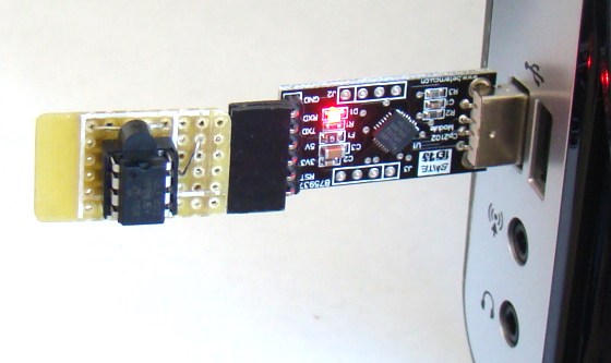
PC-based temperature data logger
Theory of operation
This project is based on Microchip's PIC12F1822 microcontroller from the enhanced mid-range PIC family. It has got 8-pins in total and the power supply voltage range of 1.8V to 5.5V. The microcontroller has four 10-bit ADC channels and one Enhanced Universal Synchronous Asynchronous Receiver Transmitter (EUSART) module for serial communication. The temperature sensor used here is MCP9701A, which is a Low-Power Linear Active Thermistor IC from Microchip Technology. The range of temperature measurement is from -40°C to +125°C. The output voltage of the sensor is directly proportional to the measured temperature and is calibrated to a slope of 19.53mV/°C. It has a DC offset of 400mV, which corresponds to 0°C. The offset allows reading negative temperatures without the need for a negative supply. The output of the sensor is fed to one of the ADC channels of the PIC12F1822 microcontroller for A/D conversion. The internal fixed voltage reference (FVR) module is configured to generate a stable 2.048 V reference voltage for A/D conversion. The use of FVR module ensures the accuracy of the A/D conversion even when the supply voltage is not stable. The PIC12F1822 microcontroller then serially transmits the 10-bit ADC output to a PC.
Modern PCs are no more equipped with serial ports and therefore this project requires a USB-UART adapter that enables very easy connection of the PIC12F1822 to the PC via the USB port. You can get them really cheap on ebay. I bought one for $3.39 (see the picture below) from here: http://cgi.ebay.com/ws/eBayISAPI.dll?ViewItem&item=370532286388
It can be directly interfaced to the TTL input and output of EUSART module of PIC12F1822. This module also provides +5 V, +3.3 V, and ground terminals. The power supply for the microcontroller circuit is derived from the same +5 V and ground pins.
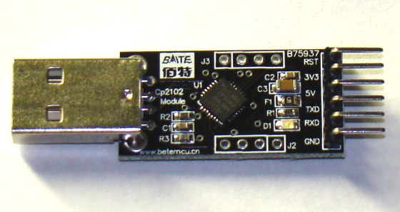
USB-UART module
On PC's side, the open source programming language Processing is used to receive the ADC output and convert it into the actual temperature. The temperature is displayed on a graphics window on the computer screen in numeric format as well as with a wall tube thermometer looking image where the level of alcohol rises with increasing temperature. A clickable Start/Stop button also appears on the window to enable or disable the data logging.
Circuit diagram
The circuit diagram of this project is pretty simple. The microcontroller reads the temperature sensor's output through RA2/AN2 pin and convert it to a 10-bit digital number. The Tx (RA0) and Rx (RA1) port of the EUSART module are connected to the corresponding pins of the USB-UART module. The microcontroller runs at 4.0 MHz using an internal clock source. Although I have disabled the MCLR function here, you can use it for an external reset if you want.
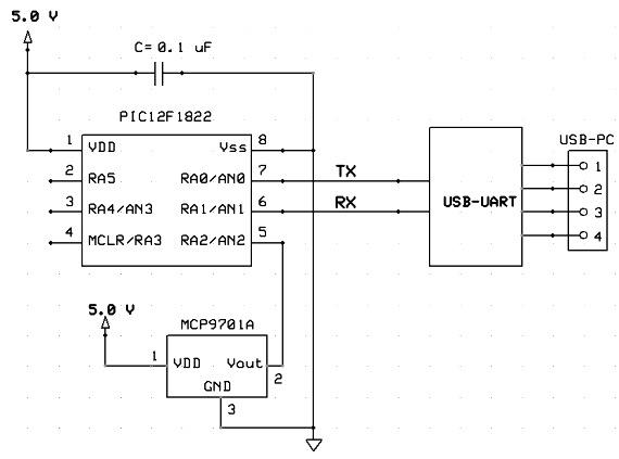
Circuit diagram
I soldered the above circuit (except the USB-UART adapter) on a general purpose prototyping board with a 6-pin female header connector so that it could be easily plugged into the male header pins of the USB-UART adapter (shown below).
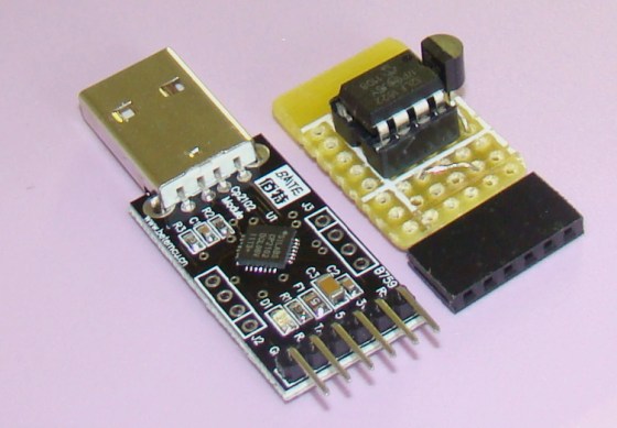
Microcontroller and USB-UART modules
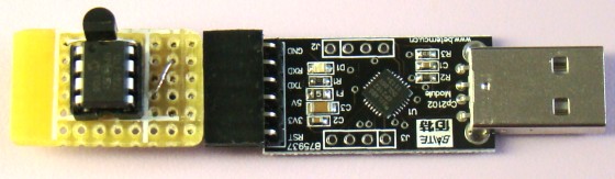
Two modules plugged into each other
Software
The firmware for PIC12F1822 is developed in C and compiled with mikroElektronika's mikroC Pro for PIC compiler. The compiler does provide an ADC library but that uses the external supply voltage as a reference for A/D conversion. In order to configure the FVR module to generate a fixed 2.048V for A/D conversion, you have to write your own code for ADC operation. The ADC sample is taken every 2 sec and is sent to the PC through USB-UART module as two bytes. The complete source code is provided below with comments. It can be compiled with the demo version of mikroC Pro for PIC compiler. Make sure that you select the internal clock source at 4.0 MHz from Project->Edit window.
/*
  Project: PC thermometer
  Description: Sends ADC samples to a PC through UART port
  MCU: PIC12F1822 running at 4.0 MHz internal clock
   Written by: Rajendra Bhatt
  Date:       Oct 10, 2011
*/

unsigned int adc_value;
unsigned short MS_Byte, LS_Byte;
char error;
int i;
void main() {
 ANSELA = 0b00000100;  // RA2 analog input
  TRISA  = 0b00100110;  // RA1, RA2, RA5 inputs
 PORTA = 0;
 OSCCON = 0b01101000;
 UART1_Init(9600);
 Delay_ms(100);

 // Configure FVR to 2.048 V for ADC
  FVRCON = 0b11000010 ;

  // Configure ADCON1
   ADCON1.ADPREF0 = 1; // Vref+ is 2.048 V
  ADCON1.ADPREF1 = 1;
  ADCON1.ADCS0   = 0; // Use conversion clock, Fosc/2
  ADCON1.ADCS1   = 0; // Fosc = 500 KHz
  ADCON1.ADCS2   = 0;
  ADCON1.ADFM    = 1;  // result is right Justified

  // Configure ADCON0 for channel AN2
  ADCON0.CHS0 = 0;
  ADCON0.CHS1 = 1;
  ADCON0.CHS2 = 0;
  ADCON0.CHS3 = 0;
  ADCON0.CHS4 = 0;
  ADCON0.ADON = 1;  // enable A/D converter

do {
  ADCON0.F1 = 1;     // start conversion, GO/DONE = 1
   while (ADCON0.F1); // wait for conversion
  MS_Byte = ADRESH;
  LS_Byte = ADRESL;
  UART1_Write(MS_Byte);
  Delay_ms(50);
  UART1_Write(LS_Byte); // Line Feed
  delay_ms(2000);
 } while(1);
}
Download the complete mikroC code
As I mentioned earlier, the PC application is developed using the Processing programming language. Processing is an open-source software development environment designed for simplifying the process of creating digital images, animations and interactive graphical applications. It is free to download and operates on Mac, Windows, and Linux platforms. I have written a simple application here that receives the 10-bit ADC sample from the serial port, converts it to temperature, and display it on the computer screen. The Processing serial library allows for easily reading and writing data to and from the serial ports. Read more about the Processing serial library HERE.
You should import the Processing Serial library first before accessing the serial port. This can be done by,
import processing.serial.*;
Next, you can open a serial port as
PIC_Board = new Serial(this, "COM6", 9600);
In my case, the USB-UART module appear as COM6, you should find the right COM number to make it work for you, which you can find out from the Device Manager tool in Windows.
Once the two bytes of ADC data are received serially, the actual temperature is retrieved by applying the sensor specific conversion factors. For MCP9701A, the conversion equation would be,
   temp = MS_Byte*256 + LS_Byte;
   tempC = (2*temp - 400)/19.5;  // Factor 2 corresponds to VREF = 2.048 V
    tempF = ((tempC*9)/5) + 32;
A clickable Start/Stop button is also provided on the display window. The Processing Mouse functions are used to detect a mouse press over the button. When the Start is pressed, data logging begins and the label on the button turns into 'Stop'. If Stop is pressed, the data logging is paused. The temperature samples are recorded along with the date and time stamp (from PC) into an ASCII file. Every time the Start is pressed, the program creates a new ASCII log file. The name of the file contains the current system date and time so that there won't be any overwriting of files. However, the data are temporarily stored into the PC's RAM and are transferred to the ASCII file on the hard drive only after pressing the Stop button.
The Processing source code and exported applications can be downloaded from the following link.
Download the Processing source code
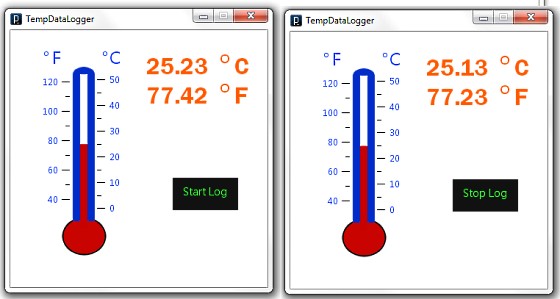
PC application window
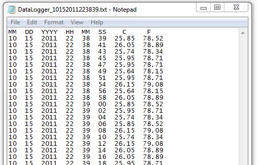
Sample ASCII log file
Future enhancements
There is a lot of room for improvements in this project. The sampling interval of the data logger is currently hard coded into the firmware of the PIC12F1822 microcontroller. However, both the firmware and the PC application can be modified to make the sampling time user-configurable from the application window. Similarly, a plotting program can also be added to the Processing application to display the temperature profile from the logged files.
Update
Conversion formula for MCP9701A
Resolution of A/D conversion (Vref = 2.048V) = 2.048 V/1024 = 2 mV/count
=> Equivalent voltage for 10-bit ADC output (Count) = 2*Count (mV)
=> Temperature (°C) = (Voltage – Sensor Offset)/Sensor conversion coefficient,
where Sensor Offset = 400 mV and conversion coefficient = 19.5 mV/°C from datasheet.
--
With Regards,
s.m.sethupathy,
sms communication,
Tanjore -1.
mobile :9944 186 173
www.questionpaperlink.co.cc
www.sethu-panguvarthagam.blogspot.com
Heart rate measurement from fingertip
Introduction
Heart rate measurement indicates the soundness of the human cardiovascular system. This project demonstrates a technique to measure the heart rate by sensing the change in blood volume in a finger artery while the heart is pumping the blood. It consists of an infrared LED that transmits an IR signal through the fingertip of the subject, a part of which is reflected by the blood cells. The reflected signal is detected by a photo diode sensor. The changing blood volume with heartbeat results in a train of pulses at the output of the photo diode, the magnitude of which is too small to be detected directly by a microcontroller. Therefore, a two-stage high gain, active low pass filter is designed using two Operational Amplifiers (OpAmps) to filter and amplify the signal to appropriate voltage level so that the pulses can be counted by a microcontroller. The heart rate is displayed on a 3 digit seven segment display. The microcontroller used in this project is PIC16F628A.
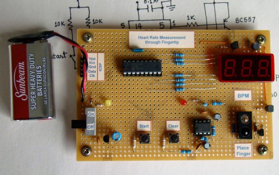
Heart rate measuring device using PIC16F628A
Theory
Heart rate is the number of heartbeats per unit of time and is usually expressed in beats per minute (bpm). In adults, a normal heart beats about 60 to 100 times a minute during resting condition. The resting heart rate is directly related to the health and fitness of a person and hence is important to know. You can measure heart rate at any spot on the body where you can feel a pulse with your fingers. The most common places are wrist and neck. You can count the number of pulses within a certain interval (say 15 sec), and easily determine the heart rate in bpm.
This project describes a microcontroller based heart rate measuement system that uses optical sensors to measure the alteration in blood volume at fingertip with each heart beat. The sensor unit consists of an infrared light-emitting-diode (IR LED) and a photodiode, placed side by side as shown below. The IR diode transmits an infrared light into the fingertip (placed over the sensor unit), and the photodiode senses the portion of the light that is reflected back. The intensity of reflected light depends upon the blood volume inside the fingertip. So, each heart beat slightly alters the amount of reflected infrared light that can be detected by the photodiode. With a proper signal conditioning, this little change in the amplitude of the reflected light can be converted into a pulse. The pulses can be later counted by the microcontroller to determine the heart rate.
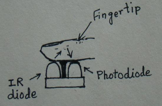
Fingertip placement over the sensor unit
Circuit Diagram
The signal conditioning circuit consists of two identical active low pass filters with a cut-off frequency of about 2.5 Hz. This means the maximum measurable heart rate is about 150 bpm. The operational amplifier IC used in this circuit is MCP602, a dual OpAmp chip from Microchip. It operates at a single power supply and provides rail-to-rail output swing. The filtering is necessary to block any higher frequency noises present in the signal. The gain of each filter stage is set to 101, giving the total amplification of about 10000. A 1 uF capacitor at the input of each stage is required to block the dc component in the signal. The equations for calculating gain and cut-off frequency of the active low pass filter are shown in the circuit diagram. The two stage amplifier/filter provides sufficient gain to boost the weak signal coming from the photo sensor unit and convert it into a pulse. An LED connected at the output blinks every time a heart beat is detected. The output from the signal conditioner goes to the T0CKI input of PIC16F628A.

IR sensors and signal conditioning circuit
The control and display part of the circuit is shown below. The display unit comprises of a 3-digit, common anode, seven segment module that is driven using multiplexing technique. The segments a-g are driven through PORTB pins RB0-RB6, respectively. The unit's, ten's and hundred's digits are multiplexed with RA2, RA1, and RA0 port pins. A tact switch input is connected to RB7 pin. This is to start the heart rate measurement. Once the start button is pressed, the microcontroller activates the IR transmission in the sensor unit for 15 sec. During this interval, the number of pulses arriving at the T0CKI input is counted. The actual heart rate would be 4 times the count value, and the resolution of measurement would be 4. You can see the IR transmission is controlled through RA3 pin of PIC16F628A. The microcontroller runs at 4.0 MHz using an external crystal. A regulated +5V power supply is derived from an external 9 V battery using an LM7805 regulator IC.
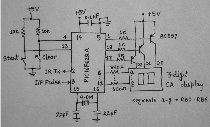
Microcontroller and Display Circuit
Software
The firmware does all the control and computation operation. In order to save the power, the sensor module is not activated continuously. Instead, it is turned on for 15 sec only once the start button is pressed. The pulses arriving at T0CKI are counted through Timer0 module operated in counter mode without prescaler. The complete program written for MikroC compiler is provided below. An assembled HEX file is also available to download.
/*
  Project: Measuring heart rate through fingertip
  Copyright @ Rajendra Bhatt
  January 18, 2011
  PIC16F628A at 4.0 MHz external clock, MCLR enabled
 */

sbit IR_Tx at RA3_bit;
sbit DD0_Set at RA2_bit;
sbit DD1_Set at RA1_bit;
sbit DD2_Set at RA0_bit;
sbit start at RB7_bit;
unsigned short j, DD0, DD1, DD2, DD3;
unsigned short pulserate, pulsecount;
 unsigned int i;
//-------------- Function to Return mask for common anode 7-seg. display
unsigned short mask(unsigned short num) {
 switch (num) {
 case 0 : return 0xC0;
 case 1 : return 0xF9;
 case 2 : return 0xA4;
  case 3 : return 0xB0;
 case 4 : return 0x99;
 case 5 : return 0x92;
 case 6 : return 0x82;
 case 7 : return 0xF8;
 case 8 : return 0x80;
 case 9 : return 0x90;
 } //case end
}

void delay_debounce(){
  Delay_ms(300);
}

void delay_refresh(){
 Delay_ms(5);
}

void countpulse(){
 IR_Tx = 1;
 delay_debounce();
 delay_debounce();
 TMR0=0;
 Delay_ms(15000);  // Delay 15 Sec
 IR_Tx = 0;
  pulsecount = TMR0;
 pulserate = pulsecount*4;
}

void display(){
  DD0 = pulserate%10;
  DD0 = mask(DD0);
  DD1 = (pulserate/10)%10;
  DD1 = mask(DD1);
  DD2 = pulserate/100;
  DD2 = mask(DD2);
   for (i = 0; i<=180*j; i++) {
    DD0_Set = 0;
    DD1_Set = 1;
    DD2_Set = 1;
    PORTB = DD0;
    delay_refresh();
    DD0_Set = 1;
    DD1_Set = 0;
    DD2_Set = 1;
    PORTB = DD1;
     delay_refresh();
    DD0_Set = 1;
    DD1_Set = 1;
    DD2_Set = 0;
    PORTB = DD2;
    delay_refresh();
    }
  DD2_Set = 1;
}

void main() {
 CMCON = 0x07;    // Disable Comparators
  TRISA = 0b00110000; // RA4/T0CKI input, RA5 is I/P only
 TRISB = 0b10000000; // RB7 input, rest output
 OPTION_REG = 0b00101000; // Prescaler (1:1), TOCS =1 for counter mode
 pulserate = 0;
 j = 1;
 display();
  do {
  if(!start){
   delay_debounce();
   countpulse();
   j= 3;
   display();
  }
 } while(1);  // Infinite loop
}
Output
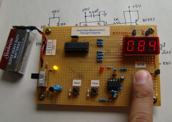
The use of this device is very simple. Turn the power on, and you will see all zeros on display for few seconds. Wait till the display goes off. Now place your forefinger tip on the sensor assembly, and press the start button. Just relaxed and don't move your finger. You will see the LED blinking with heart beats, and after 15 sec, the result will be displayed.
--
With Regards,
s.m.sethupathy,
sms communication,
Tanjore -1.
mobile :9944 186 173
www.questionpaperlink.co.cc
www.sethu-panguvarthagam.blogspot.com
DS18B20 pic
DS18B20.
DS18B20 is 1-Wire interface digital thermometer that require one port pin (and ground) for communication, has a unique 64-bit serial code stored in an onboard ROM, can measure temperatures from -55C to +125 C (-67F to +257F),and user-selectable resolution from 9 to 12 bits.
Pin assignment, pin description and block diagram of DS18B20 shown below. The DS18B20 can be powered by an external supply on the Vdd pin, or powered by the DQ pin (parasite power mode). Stealing power from DQ pin saves a wire but comunication with it is more complicate than using external power supply. For more detail about powering the DS18B20 can be found in the powering the DS18B20 section of its datasheet.


DS18B20 Memory.
Scratchpad is 9 bytes of SRAM that organized as figer shown below. The first two bytes (byte 0 and byte 1) are read-only memory that contain the LSB and the MSB of the temperature register. Bytes 2 and 3 provide access to TH and TL registers. Byte 4 is a configuration register. Bytes 5,6 and 7 are reserved. Byte 8 is read-only and contains CRC code (cyclic redundancy check) for byte 0 through byte 7 of the scratchpad.

The output temperature data from DS18B20 is calibrated in degree centigrade and the default resolurion at power up is 12-bit. The temperature register format shown below, where as sign bits (S) indicate if the temperature is positive (S=0) or negative (S=1).


To access the DS18B20's data, 3 steps sequence as follows is need.
1. Initalization. All transections on the 1-wire bus begin with an initalization sequence. It consists of a reset pulse transmitted by the bus master followed by presence pulse transmitted by the slave. Timing for the reset and presence pulse is shown below.

2. Issue a ROM command after the bus master has detected a presence pulse. ROM commands are : Search ROM[F0h], Read ROM[33h], Match ROM[55h], Skip ROM[CCh] and Alarm Search[ECh].
3. Issue a DS18B20 function command after a ROM command. A ROM command is to select which DS18B20 that the master want to communicate with. A function command allows the master to read and to write from the DS18B20's scratchpad, etc. DS18B20 function commands are: Convert T[44h], Write Scratchpad[4Eh], Read Scratchpad[BEh], Copy Scratchpad[48h], Recall E2[B8h], and Read Power Supply[B4h].
It is very important to follow this sequence every time the DS18B20 is accessed. Exceptions to this rule are Search ROM[F0] and Alarm Search[EC] commands. The master must return to step 1 after issue either of those ROM commands.
Read/Write signaling.
All data and commands are transmitted least significant bit first over the 1-Wire bus. The figure shown below is Read/Write timing diagram. All Read/Write time slots must be 60 usec in duration with a minimum of a 1 usec recovery time between individual read/write slots. To write "1" the bus master pull low and release within 15 usec. To write "0", after pulling the bus low, the bus master must continue stay low for 60 usec minimum then release the bus. To read logical from DS18B20, the bus master must pull low for at least 1 usec then release the bus then master must sample the signal within 15 usec from the start of the slot.

1-wire digital thermometer .
The schematic is shown below. Input has a DS18B20 and a 4.7K pull-up resister. For output, I have my own I2C 7 segment display moduel. You can change to a serial LCD display or something else.

The code.
Although Micko C has built-in 1-wire library but my goal for this project is to get and display temperature from DS18B20 with my own function routine.
My code is to display only positive temperature. You need extra work for negative temperature.
/*
* Project name:
DS18B20 1-wire temperature
* Copyright:
Nicholas Sirirak
* Description:
* Test configuration:
MCU: PIC16F886
Dev.Board: -
Oscillator: HS, 4.0000 MHz
Ext. Modules: -
SW: mikroC v8.2.0.0
* NOTES:
HW connection
MCU DS18B20
RB0/INT <--------> QD W/ 4.7K Ohm pull up
MCU I2C display module
SCL(RC3) <--------> SCL W/ 4.7K Ohm pull up
SDA(RC4) <--------> SDA W/ 4.7K Ohm pull up
*/
#define Skip_ROM 0xCC
#define Convert_T 0x44
#define Read_scratchpad 0xBE
#define Port_18B20 PORTB.F0
#define Tx_18B20 TRISB.F0 = 0
#define Rx_18B20 TRISB.F0 = 1
unsigned temp;
unsigned short tempL, tempH, fraction;
void delay480() {
delay_us(480);
}
char Reset_18B20() {
Tx_18B20; // Tris = 0 (output)
Port_18B20 = 0; // set pin# to low (0)
delay480(); // 1 wire require time delay
Rx_18B20; // Tris = 1 (input)
delay_us(60); // 1 wire require time delay
if (Port_18B20 == 0) { // if there is a presence pluse
delay480();
return 0; // return 0 ( 1-wire is presence)
} else {
delay480();
return 1; // return 1 ( 1-wire is NOT presence)
}
}
void Write_18B20 (char Cmd){
char i;
Rx_18B20; // set pin# to input (1)
for(i = 0; i < 8; i++){
if((Cmd & (1<<i))!= 0) {
// write 1
Tx_18B20; // set pin# to output (0)
Port_18B20 = 0; // set pin# to low (0)
delay_us(1); // 1 wire require time delay
Rx_18B20; // set pin# to input (release the bus)
delay_us(60); // 1 wire require time delay
} else {
//write 0
Tx_18B20; // set pin# to output (0)
Port_18B20 = 0; // set pin# to low (0)
delay_us(60); // 1 wire require time delay
Rx_18B20; // set pin# to input (release the bus)
}
}
}
char Read_18B20 (){
char i,result = 0;
Rx_18B20; // TRIS is input(1)
for(i = 0; i < 8; i++){
Tx_18B20; // TRIS is output(0)
Port_18B20 = 0; // genarate low pluse for 2us
delay_us(2);
Rx_18B20; // TRIS is input(1) release the bus
if(Port_18B20 != 0) result |= 1<<i;
delay_us(60); // wait for recovery time
}
return result;
}
void main(){
TRISB = 0;
ANSELH = 0;
I2C_Init(100000); //initial I2C
delay_ms(1000);
while(1){
if(!Reset_18B20()){
Write_18B20(Skip_ROM);
Write_18B20(Convert_T);
delay_ms(750);
Reset_18B20();
Write_18B20(Skip_ROM);
Write_18B20(Read_scratchpad);
tempL = Read_18B20();
tempH = Read_18B20();
if(tempL.F3) fraction = 1;
else fraction = 0;
tempL >>= 4;
tempH <<= 4;
tempH += tempL;
tempL = Dec2Bcd(tempH);
I2C_Start(); //issue start signal
I2C_Wr(0x68); //send slave address and write signal
I2C_Wr(0x40);
I2C_Wr(tempL);
if(fraction) I2C_Wr(0x5C);
else I2C_Wr(0x0C);
I2C_Stop();
}
}
}
Note.

--
With Regards,
s.m.sethupathy,
sms communication,
Tanjore -1.
mobile :9944 186 173
www.questionpaperlink.co.cc
www.sethu-panguvarthagam.blogspot.com


