


UM3561 SIREN GENERATOR DESIGN
UM3561 is an excellent ROM IC that can generate Multi siren tones simulating Police siren, Ambulance siren, Fire brigade siren and Machine gun sound. This 8 pin low power IC can work down to 2.4 volts.
The UM 3561 is a low cost siren generator designed for use in toy applications. The IC has an inbuilt oscillator and tone selection pins. It is easy to make a siren generator with only a few external components. Only one external resistor and a speaker driver transistor are sufficient to make a simple siren generator.
Inside the UM3561
Inside the IC, there is an oscillator circuit and the frequency of oscillations is controlled by the external resistor connected to OSC 1(Pin 7) and OSC2 (Pin 8). A 220 K resistor will give satisfactory results. The oscillations thus generated will be then transferred to a control circuit which function based on the tone selection through the connections of SEL 1 (Pin 6) and SEL2 (Pin 1) . The control circuit passes the signal to an address counter and then to the ROM. The tone pulses thus generated will be available from the output pin 3. Since the sound is weak, an amplifier is necessary to get loud sound. A single NPN transistor will amplify the sound.

Pin Assignment
Pin 1 Tone Sel.2
Pin 2 Gnd
Pin 3 Output
Pin 4 NC- Used for testing purpose
Pin 5 +3V
Pin 6 Tone Sel .1
Pin 7 Osc 1
Pin 8 Osc 2
Tone Selection
By changing the pin connections of Sel.1 (Pin6) and Sel. 2(Pin 1) it is easy to change the siren tones.
Sel 1Sel 2Tone
Pin 6 Pin 1
NC NC Police siren
+3V NC Fire Engine sound
Gnd NC Ambulance Siren
NC +3V Machine Gun sound
UM3651 Siren Generator Circuit Diagram

Absolute Maximum ratings
Supply voltage Min. 2.4VTyp 3V Max 3.5V
Operating current Min - -180 uA
--
With Regards,
s.m.sethupathy,
sms communication,
Bangalore.
mobile : 09944 186 173 ,0 889 246 250 1
www.questionpaperlink.co.cc
www.sethu-panguvarthagam.blogspot.com
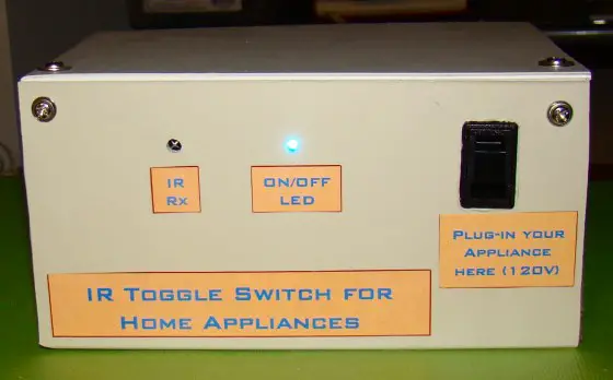
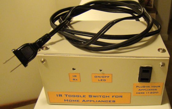
A very simple IR remote control switch for an electrical appliance
The original circuit diagram for this project was published in the May 2005 issue of theElectronics For You magazine. The circuit diagram below is mostly the same. It uses a TSOP1738 IR receiver module at the input side to receive the 38 KHz frequency IR pulses from the remote control. Under normal condition, the output pin of the IR module is at logic High, which means the transistor T1 (BC557 PNP) is cut-off and its collector terminal is at logic Low. The collector of T1 drives the clock line of the CD4017 decade counter.
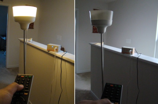
Now lets see what happens when somebody faces a TV or DVD remote towards the TSOP1738 and presses any key on it. The TSOP 1738 module receives the train of 38 KHz IR pulses from the remote, that makes its output to oscillate too. These pulses are inverted at the collector of T1, which finally go to the clock input of the decade counter. The arriving pulses could increment the CD4017 counter at the same rate (38 KHz), but because of the presence of the RC filter circuit (R1 = 100K, C1 = 10 uF) between the collector and the ground, the train of pulses appear as a single pulse to the counter. Thus, on each key pressing, the CD4017 counter advances only by a single count. When the user releases the key, the C1 capacitor discharges through the R1 resistor, and the clock line is back to zero. So every time the user presses and releases a key on the remote, the CD4017 counter receives a single pulse at its clock input.
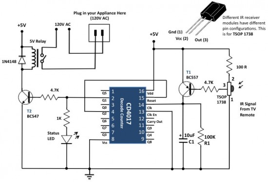
The power supply for the circuit can be derived from the mains AC itself using a step down transformer and a bridge-rectifier circuit. For +5V power supply, the LM7805 regulator IC can be used as shown below.

 |  |
--
With Regards,
s.m.sethupathy,
sms communication,
Bangalore.
mobile : 8892462501, 09944 186 173
www.questionpaperlink.co.cc
www.sethu-panguvarthagam.blogspot.com
Clap Switch ON/OFF Circuit Diagram
Clap Switch ON/OFF Circuit Diagram

Figure shows the circuit diagram of the ' Clap Switch ON/OFF '. Here I have used a 4017 ten channel decoder integrated circuit for making this circuit. When you clapping B1 convert the sound signal into electrical signal and fed to the input of Q1 this time the Q1 is ON so the lamp will glow. Next time repeating this process but this time the Q1 is ON so the lamp will be OFF.
Parts List
| Component No: | Value |
| R1 | 1K |
| R2 | 100K |
| R3 | 10K |
| C1 | 10MF |
| Q1 | BC548 |
| U1 | 4017 |
| V1 | 230V AC |
| L1 | 230V,40W |
| U2 | BT126 |
| B1 | Mic OR Pezzo Buzzer |


