


Testing Diodes
, Posted by ADMIN at 3:31 AM
iodes can be tested using a multi meter. It is normally the resistance of the diode in both forward and reverse directions that is tested. There are however a number of points to remember when testing diodes.
Which meter?
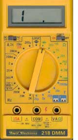
Both digital and moving coil (analogue) multi-meters are suitable for diode testing, and in many cases will have a special "diode test" range usually marked with a diode symbol. This range should always be used when testing diodes or any other semiconductor device. The reason for this is that the meter tests the diode by applying a voltage across the diode junction. The normal voltages used by the meter on other resistance ranges will not be high enough to overcome the diode's forward junction potential and so will not make the diode conduct, even in the forward direction. This would give an indication that the diode was open circuit (very high resistance). If the diode range is used, the test voltage applied by the meter will be high enough to overcome the forward junction potential and the diode will conduct. Therefore in the forward direction (meter positive lead to the diode anode) the diode's resistance can be measured. The actual value will vary from device to device and from meter to meter, so a precise value cannot be given. With a good silicon diode however, a reading in the forward direction of about 1kΩ could be expected, rather less with germanium diodes. With the meter leads reversed, an out of range (infinity) or open circuit reading (usually indicated by a display something like "1." on a digital meter) should be expected.
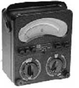
A problem exists with some meters when measuring LEDs. The applied voltage, even on the diode range is not enough to make the diode conduct. LEDs cannot be tested with a meter unless its output voltage is more than about 1.5V. The voltage on most digital meters is less than this, so they indicate that LEDs are high resistance (open circuit) when they are OK. Some meters are available that are able to test LEDs. The Avo 8 has a probe voltage of about 1.5V when using the Ωx100 range. It must be remembered however that the polarity of the probe voltage on analogue meters is reversed compared to digital meters. When measuring resistance with an analogue meter on any range the BLACK lead is positive and the RED lead is negative. This means that when using the Avo, you must connect black to anode and red to cathode to measure the FORWARD resistance of the diode. Also with the Avo you should not use the Ωx10K range when measuring any semiconductor device. The probe output voltage on this range can be about 15V, quite enough to destroy a semiconductor junction! Some multi-meters are available, which instead of displaying the resistance of the diode on the diode test range, display the junction potential (in volts).
Making the tests
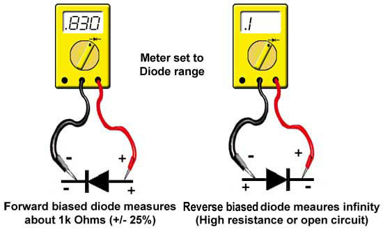
The diagram below shows how to connect a digital meter to test the diode. There are a number of things to remember:
- • Make sure you are using the diode range.
- • Using a digital meter, connect the black lead to the cathode and red to the anode (forward bias - around 1kΩ).
- • Reverse the meter connections (reverse bias - infinity reading).
REMEMBER - If you are using an analogue meter the above polarities are reversed.
SOME METERS give a reading of the junction potential (in volts) CHECK YOUR METER INSTRUCTIONS.
Identifying the Connections
The cathode connection of a diode is marked in various ways. In the case of a bridge rectifier package, the AC input terminals and the DC output terminals are usually marked with a sine wave symbol and plus/minus signs respectively, as shown.
Bridge rectifiers can be tested as ordinary diodes as long as each diode is tested separately. The package pins should be compared with a diagram of the internal layout of the four diodes. Then identify individual diode cathode and anode connections, so you can test each diode´s forward and reverse resistance.
Fault Indications
Short Circuit
Diodes can be damaged by high voltages, especially diodes working in high voltage or high power applications such as power supplies, and as a result will usually go short circuit 0Ω when measured in either direction. When a diode in a power supply goes short circuit, large currents can flow and obvious damage occurs such as "cooked" diodes and / or blown fuses. Short circuit diodes that are not obviously damaged show 0Ω or very low resistance in both forward and reverse directions.
Open Circuit
Occasionally, diodes (especially small signal diodes) may go open circuit, and read very high resistance or infinity (shown as 1 on digital meters) in both forward and reverse directions.
Leaky
Sometimes a signal diode may become "leaky". While its forward resistance may be normal, its reverse resistance may be lower than the expected infinity. Often this fault could only be measured with the diode removed from the circuit it is working in because of the parallel resistances of other components connected across the diode.
Zener Diodes
Zener diodes exhibit similar faults to other diodes, but in addition may become "noisy". They do not make a noise but the normally very stable voltage across them suffers from very rapid fluctuations similar to the spiky waveform you would see on an oscilloscope when looking at an audio signal that was just a constant hiss, (also called noise since it is sometimes present as "background noise"). As Zener diodes are often used to stabilise power supply lines, this "noise" can give rise to strange faults, depending on what is being supplied by the power supply in question. The moral is - If a circuit is behaving strangely, and noise on the power supply is suspected, check any Zener diode stabilising that line by substituting it with a known good diode. All Zener diodes have a defined voltage, and if the voltage measured across them under working conditions, is not what is printed in the circuit manual (or on the diode if you can see the markings), then the diode is faulty, (probably open circuit) and must be changed.


Currently have 0 comments: