PIC Timers and Counters (Part 1)
Description
PIC microcontrollers are equipped with one or more precision timing systems known as Timers. They can be used to perform a variety of time precision functions, such as generating events at specific times, measuring the duration of an event, keeping date and time record, counting events, etc. The main component of a timer module is a free running binary counter that increments for each incoming pulse. Since it runs independently, it can count pulses concurrently with the main program execution. A PIC16F688 microcontroller has two built-in hardware timer modules: Timer0 and Timer1. Today's lab lesson will explore the functionality of the Timer0 module.
Required Theory
The fundamental concept of a timer/counter module is discussed in Timers and Counters. It is simply an independent binary counter that can be configured to count instruction cycles or to count external clock pulses. The Timer0 module in a PIC16F688 microcontroller is an 8-bit synchronous counter that stores the value for the counter in the special function register called TMR0. This register can be read or written at any time by software. If you write a value to it, the counter will start incrementing from there.
When the Timer0 module is driven by the processor's instruction clock, it is said to operate as a timer because it increments at a constant rate (defined by the processor clock) and if you know the number of pulses counted, you can derive how much time has elapsed. The Timer0 can also count external pulses arriving at the RA2 pin (11), which has the alternate name T0CKI (Timer Zero Clock Input). While counting the external pulses, it is said that it operates as a counter. We will discuss the two modes of Timer0 separately.
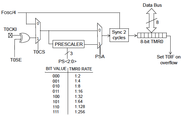
Block diagram of Timer0 Module (Source: Microchip)
Timer mode
Timer mode is selected by clearing the TOCS bit (OPTION register, bit 5). In timer mode, the TMR0 register increments every instruction cycle. As an 8-bit register, TMR0 can count from 00 to FF (255). When it reaches its maximum value, FF, and is incremented further, it rolls over to 00. This register overflow is recorded by the T0IF (Timer0 Interrupt Flag) bit of the INTCON (Interrupt Control) register by being set to 1. The T0IF bit set can trigger an interrupt (known as Timer0 Interrupt), if enabled. [An interrupt is an asynchronous signal calling for processor attention. It tells the microcontroller to drop whatever it's doing and go to a predefined place (the interrupt service routine or ISR) when a certain event occurs. We will discuss it more in upcoming lab sessions]. The Timer0 interrupt is enabled by setting the T0IE bit (Timer0 Interrupt Enable) of the INTCON register along with the Global Interrupt Enable (GIE) bit. This interrupt would be the indication of the time out and will occur on the every overflow of the TMR0 register. The TOIF bit must be cleared by the interrupt service routine so that the timer interrupt can take place again.
Suppose, if you are running a PIC with a 4 MHz clock, the instruction clock will be 1 MHz (1 instruction cycle = 4 clock cycles, for PIC). The counter would then be clocked every 1 μs exactly. That means, the Timer0 will take 256 μs to count from 0 to 0. By preloading the TMR0 register with a suitable value, a smaller timer interval could be selected, with time out indicated by the timer interrupt. For example, if you preload the TMR0 register with the value 206, the Timer0 overflow would occur after 50 μs.
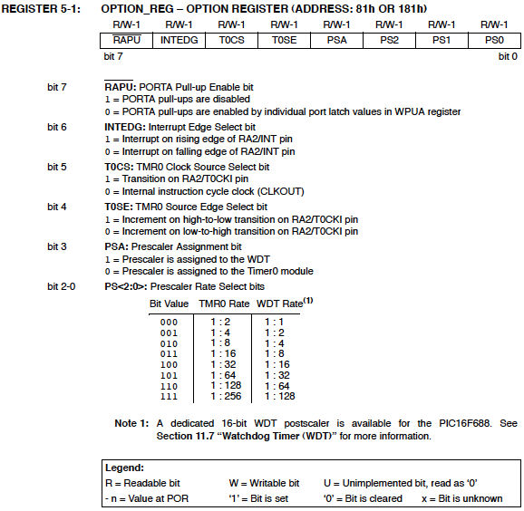
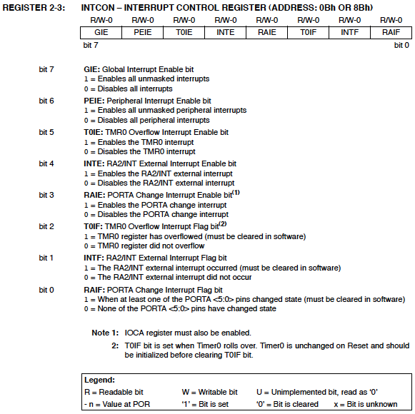
Besides, an eight bit programmable divider, known as prescaler, is also available to measure a longer time period. The prescaler is a dividing circuit between the clock source and the timer, and it divides the input frequency by one of eight binary values between 2 and 256. With 1 MHz instruction clock, the maximum timer period would be 256 x 256 μs = 65.536 ms, corresponding to the prescaler value of 256. The prescaler values are software selectable through PS0, PS1, and PS2 bits of the OPTION register. In order to use the prescaler with the Timer0 module, the PSA (Prescaler Assignment) bit of the OPTION register must be cleared. If the PSA bit is set, no prescaler will be assigned to the Timer0 module. The individual bits of the OPTION and INTCON registers are shown below.
Source: PIC16F688 Datasheet from Microchip
Counter Mode
Counter mode is selected by setting the TOCS bit in the OPTION register. In this mode, the Timer0 module counts the external clock pulses applied to its RA2/T0CKI pin. The counter will increment either on rising or falling edge of the clock pulses, which is software selectable by the T0SE (Timer0 Source Edge) bit of the OPTION register. If you set the T0SE bit, the timer will increment on the falling edge of every clock pulse arriving at the RA2/T0CKI pin. Again, the range of the counter can be extended by the use of the prescaler.
The maximum clock frequency at the T0CKI input is limited by the synchronization requirement with the internal clock. Each machine cycle (or instruction cycle) for a PIC microcontroller consists of four clock cycles, which are named as Q1, Q2, Q3, and Q4. The synchronization of T0CKI with the internal clock is accomplished by sampling the prescaler output on the Q2 and Q4 cycles of each machine cycle. Therefore, the external clock signal at T0CKI should remain high or low for at least half of the duration of the machine cycle (which is 2Tosc, Tosc is the period for the main oscillator), plus an additional resistor-capacitor delay of 20 ns. This determines the minimum value of the pulse width that enters through the T0CKI pin. The minimum time period of the input clock pulse is, therefore, 4Tosc + 40 ns, and the maximum frequency will be the reciprocal of this.
For example, if the main oscillator frequency is 4 MHz (Tosc 0.25 μs), the machine cycle will be 4 x Tosc = 1 μs long. An external clock signal going directly into the counter (without the prescaler) should be high for at least 2Tosc+20 ns = 520 ns and low for at least the same time, giving the total time period of 520 x 2 = 1040 ns. Therefore, the limit for maximum input frequeny would be 1/1040 ns = 961.5 KHz. If the prescaler is used, the electrical specification of PIC16F688 says that the external clock input must be high and low for at least 10 ns, which gives the maximum countable frequency through T0CKI pin equal to 50 MHz. Read Microchip's tutorials on Timers: Part 1 and Part 2 for further details.
Experimental Setup and Software
After reviewing the theory, lets think about doing some experiments with the Timer0 module. First, we will create an approximate 1 sec delay using the Timer0 module as a timer. The PIC16F688 runs at 4 MHz clock frequency, so the duration of a machine cycle is 1 μs. To generate 1 sec delay interval, the timer should count 1000000 machine cycles. If we use the prescaler value of 256, the required count will be reduced to 3906. Now, if we preload the TMR0 with 39, it will overflow after 256-39 = 217 counts. This gives the required number of overflows to make 3906 counts = 3906/217 = 18. With this setting, after every 18 overflows of TMR0 register (preloaded with 39), an approximate 1 sec interval is elapsed. The software below implements this to flash an LED with an approximate 1 sec interval.
/*
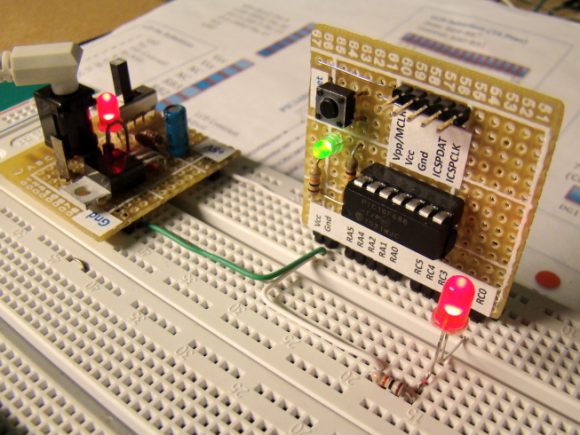
Lab 7: 1 sec timer using TIMER0 Internal Oscillator @ 4MHz, MCLR Enabled, PWRT Enabled, WDT OFF Copyright @ Rajendra Bhatt Nov 18, 2010 */ // Define LED connection sbit LED at RC0_bit; unsigned short Num; // Interrupt service routine void interrupt() { Num ++; // Interrupt causes Num to be incremented by 1 if(Num == 18) { LED = ~LED; // Toggle LED every sec Num = 0; } TMR0 = 39; // TMR0 returns to its initial value INTCON.T0IF = 0; // Bit T0IF is cleared so that the interrupt could reoccur } void main() { CMCON0 = 0x07; // Disable Comparators ANSEL = 0x00; // Disable analog channels TRISC = 0x00; // PORTC O/P LED = 0; Num = 0; OPTION_REG = 0x07; // Prescaler (1:256) is assigned to the timer TMR0 TMR0 = 39; // Timer T0 counts from 39 to 255 INTCON = 0xA0; // Enable interrupt TMR0 and Global Interrupts do { // You main programs goes here } while(1); // infinite loop } The circuit setup is the same as Lab 1: Flashing an LED. The LED is driven through RC0 pin.
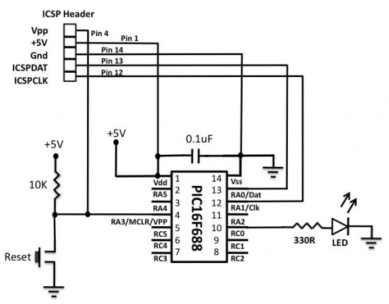
Circuit setup for flashing LED using Timer0 module
Note: The 1 sec delay that we just created is not very accurate because of the following reasons:
- In this example, the PIC16F688 microcontroller was operated with the 4 MHz internal RC oscillator, which is not highly accurate and stable. For better accuracy, an external crystal oscillator must be used.
- The timer program was written in a high-level language, so we don't know exactly how the program looked like after being compiled. For an accurate hardware timer, the programming must be done with assembly language, and any instruction that can affect the TMR0 read/write operation, should be accounted as it may introduce additional delay.
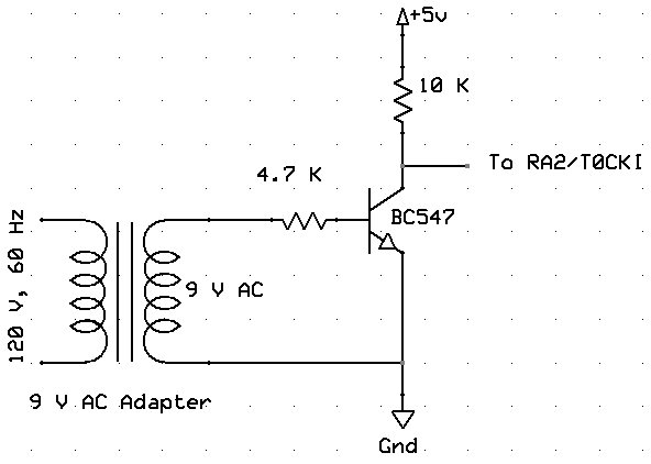
Next, the Timer0 module will be used as a counter to count the external clock pulses through RA2/T0CKI pin. The external clock source will be derived from the mains AC supply. The mains AC is 120V, 60 Hz sine wave signal. It will be first stepped down to 9 V, 60 Hz signal using an AC wall adapter. Before applying it to the T0CKI pin, it must be rectified and the peak voltage should be chopped down to +5V. The following circuit will convert the 9 V, 60 Hz AC voltage to an approximate +5 V square wave suitable for the T0CKI input.
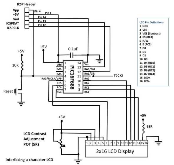
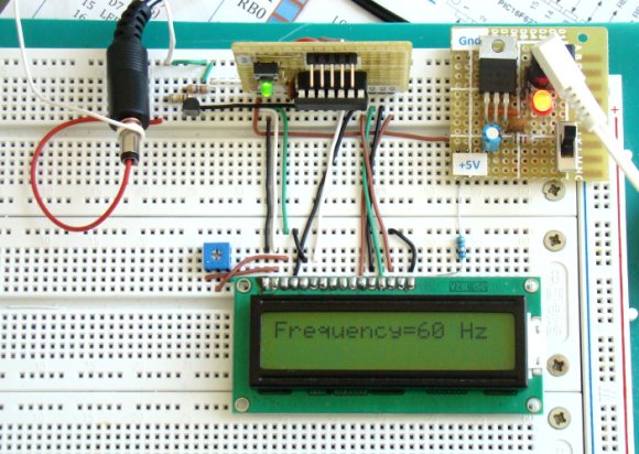
The output square wave will be connected to the RA2/T0CKI pin of the PIC16F688 microcontroller. The TMR0 will start from 0 and count the incoming pulses for 1 sec. The result will be displayed on the LCD screen. The number of pulses per second is the frequency of the incoming signal, which is 60 Hz. The circuit diagram for the microcontroller and LCD part is shown below.
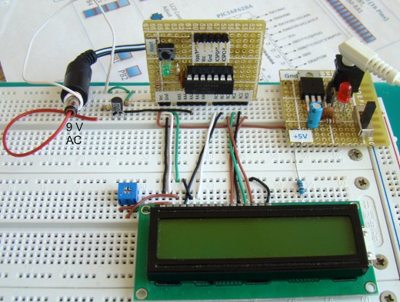
Counter circuit setup on the breadboard
Programming sequence involves initialization of ANSEL, CMCON0, and OPTION registers. The T0CS bit in the OPTION register must be set to operate the timer module as a counter.
/* Lab 7: Timer0 as a counter
Internal Oscillator @ 4MHz, MCLR Enabled, PWRT Enabled, WDT OFF Copyright @ Rajendra Bhatt November 18, 2010 */ // LCD module connections
sbit LCD_RS at RC4_bit; sbit LCD_EN at RC5_bit; sbit LCD_D4 at RC0_bit; sbit LCD_D5 at RC1_bit; sbit LCD_D6 at RC2_bit; sbit LCD_D7 at RC3_bit; sbit LCD_RS_Direction at TRISC4_bit; sbit LCD_EN_Direction at TRISC5_bit; sbit LCD_D4_Direction at TRISC0_bit; sbit LCD_D5_Direction at TRISC1_bit; sbit LCD_D6_Direction at TRISC2_bit; sbit LCD_D7_Direction at TRISC3_bit; // End LCD module connections // Define Messages
char message1[] = "Frequency= Hz"; char *freq = "00"; void Display_Freq(unsigned int freq2write) {
freq[0] = (freq2write/10)%10 + 48; // Extract tens digit freq[1] = freq2write%10 + 48; // Extract ones digit // Display Frequency on LCD Lcd_Out(1, 11, freq); } void main() {
CMCON0 = 0x07; // Disable Comparators ANSEL = 0x00; // Disable analog channels TRISC = 0x00; // PORTC O/P TRISA = 0b00001100; // RA2/T0CKI input, RA3 is I/P only OPTION_REG = 0b00101000; // Prescaler (1:1), TOCS =1 for counter mode Lcd_Init(); // Initialize LCD Lcd_Cmd(_LCD_CLEAR); // CLEAR display Lcd_Cmd(_LCD_CURSOR_OFF); // Cursor off Lcd_Out(1,1,message1); // Write message1 in 1st row do {
TMR0=0; Delay_ms(1000); // Delay 1 Sec Display_Freq(TMR0); } while(1); // Infinite loop } References:
--
With Regards,
s.m.sethupathy,
sms communication,
Tanjore -1.
mobile :9944 186 173
www.questionpaperlink.co.cc
www.sethu-panguvarthagam.blogspot.com




Currently have 0 comments: