Digital I/O Ports in PIC16F688
PIC16F688 is a 14-pin flash-based, 8-bit microcontroller. It can be obtained in different packages, but the DIP (Dual In-line Package) version is recommended for prototyping. The figure below shows a PIC16F688 microcontroller in DIP chip, and its pin outs.

Most of the pins are for input and output, and are arranged as PORTA (6) and PORTC (6), giving a total of 12 I/O pins. All of these can operate as simple digital I/O pins but they do have more than one function. For example, eight of total 12 I/O pins also serve as analogue inputs for the internal analog-to-digital converter (ADC). Similarly, the PORTA pins RA0 and RA1 are also used to serially load an user program into the PIC16F688 flash memory. The mode of operation of each pin is selected by initializing various control registers inside the chip. All these options will be discussed later on.
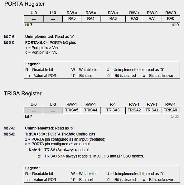
PORTA
PORTA is a 6-bit wide, bidirectional port. A bidirectional port is one that can act as either an input port, to receive information from external circuitry, or an output port, to give information to external circuitry. The direction of the PORTA pins is controlled by the TRISA register. Setting a TRISA bit (= 1) will make the corresponding PORTA pin an input, and clearing a TRISA bit (= 0) will make the corresponding PORTA pin an output. The RA3 pin is an exception because it is input only and so its TRISA bit will always read as '1'. The TRISA register controls the direction of the PORTA pins, even when they are being used as analog inputs. Therefore, the user must ensure the bits in the TRISA register are maintained set when using them as analog inputs. I/O pins configured as analog input always read '0'.
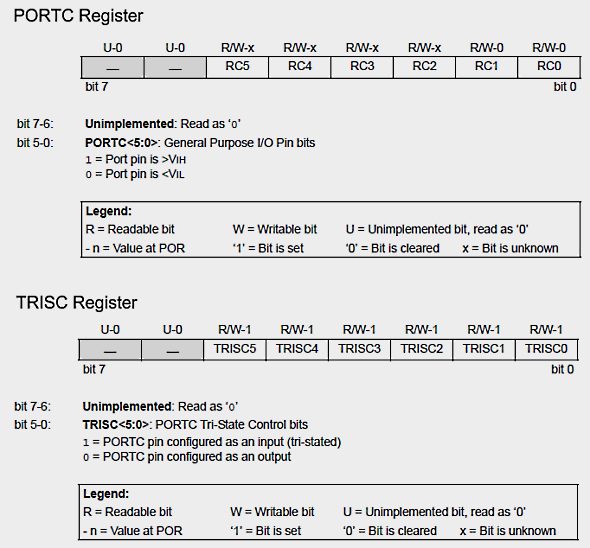
PORTC
Similar to PORTA, PORTC also has 6 bidirectional I/O pins. Each of the pin can be selected as input or output by setting or clearing the corresponding bit in the TRISC register.
Important
PIC16F688 has two analog voltage comparators and eight 10-bit ADC channels. The inputs to the comparators are multiplexed with I/O port pins RA0, RA1, RC0 and RC1, while the outputs are multiplexed to pins RA2 and RC4. On a power-on reset, RA0, RA1, RC0, and RC1 are configured as analog inputs, as controlled by the CMCON0 register. In order to use these pins as digital inputs, the comparators must be turned OFF. This can be done by assigning decimal value 7 to CMCON0 register (CMCON0=0b00000111).
Similarly, the PIC16F688 port pins that are multiplexed with ADC channel inputs are also configured as analog inputs on a power-on reset. The ANSEL register must be initialized to decimal 0 (ANSEL=0b00000000) to configure all ADC channels as digital inputs. The CMCON0 and ANSEL registers will be discussed in more detail later.
--
With Regards,
s.m.sethupathy,
sms communication,
Tanjore -1.
mobile :9944 186 173
www.questionpaperlink.co.cc
www.sethu-panguvarthagam.blogspot.com


Currently have 0 comments: